Toy Train Layout Wiring - Engine Safety Relays P.2of2
| Basic | Intermediate | Advanced | Wire Management | Bus Wiring | 120V Train Room |
| Glossary | Wire Sizes | Switches | Load Calculations | Soldering | Troubleshooting |
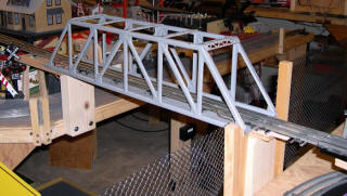
see Lift Bridge with Lift Assist Serving the Two Main Lines on P. 1
see Lift Bridge with Lift Assist Serving the Outside Main Line on P. 1
Lionel 022 Switch Wired to Control Track Power
with Relay for Engine Protection
When an access bridge can't switch the track power, the bridge can switch a relay.
Pre 2004 Layout Wire Color Coding
Red #14 for Elevated Table Track and
Orange #14 for Bridge ascending/descending
Variable Voltage,
White for Transformer Common, Purple for Switched Common, Red #16 is
16V Switch Power
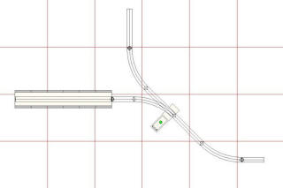
The 317 Bridge Track and the Loop Track
are on Different Voltage Sources
The 022 approach track at the bottom of the diagram must be dead
when the bridge is open
and the switch is set to go left into the hole.
Power must stay on the loop when bridge is open
and switch is set to continue right around the loop.
A relay does the trick.
 |
 |
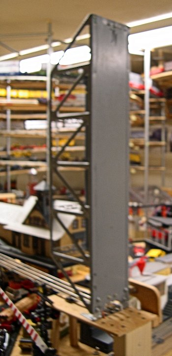
Bridge Acts as a Switch to Control Track Power
| The magnetic
cabinet catch holds the steel bridge in up postition. Flexible wires power the bridge track 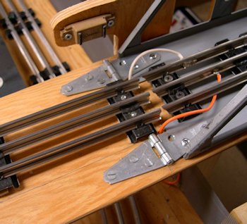 |
The open end of
the metal bridge closes the switch contacts. 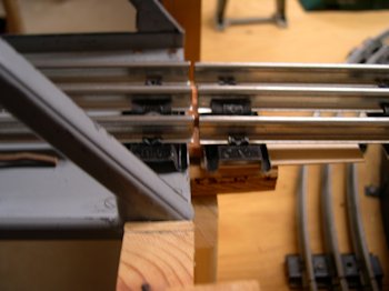 |
 |
The switch
contact points close the switch when bridge is down. 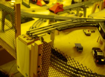 022 Switch Controls Track Power 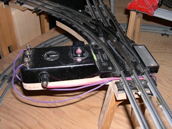 |
The distance between the right
insulating pins and the 022 switch must be long enough
so the train will not coast through the 022 switch.
When the turnout is aligned toward the bridge the approach track commons
are disconnected at the relay. When the bridge is down the commons
are
connected through bridge contacts and the train can proceed.
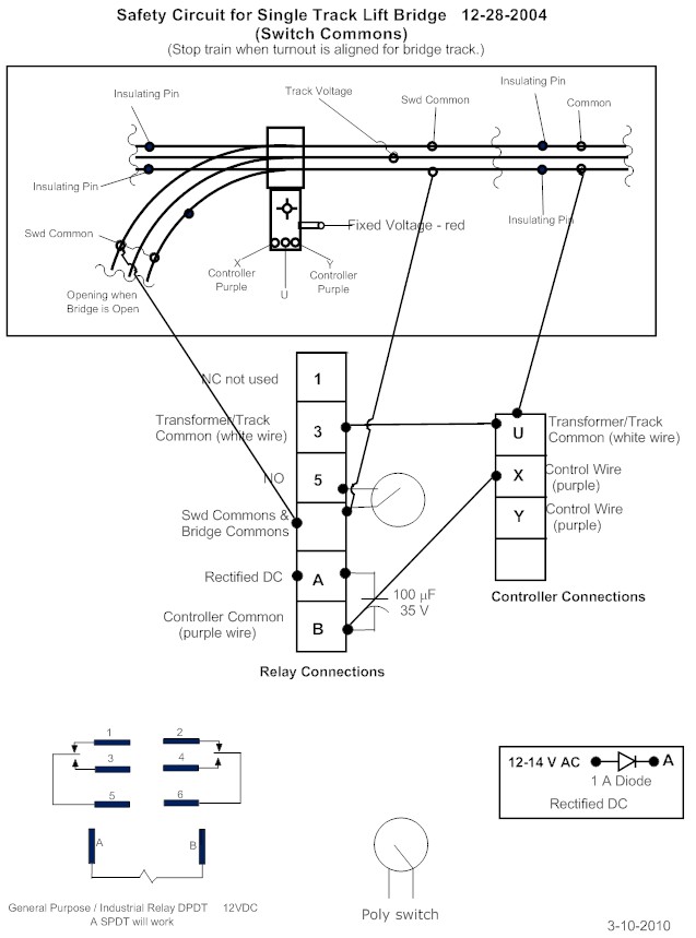
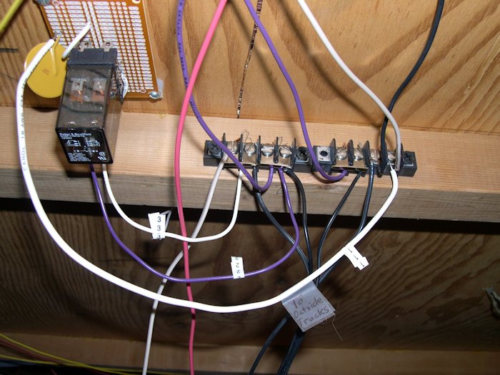
Wiring Notes
Use a Latching Relay. Relay used here is a Tyco Electronics/P&B
K10P-11D15-12
DPDT 30 VDC / 120 VAC, 10 A at 277 VAC with a
General Purpose/Industrial Relay DPDT SOCKET MT 12VDC.
Diode Hint
Use a digital multimeter to test the polarity of a diode in the
event the polarity markings
are absent or missing. Simply turn the meter unit on and turn the
dial to measure "Ohms."
Hold the black (negative) test probe to one metal leg of the diode
and the red (positive)
test probe to the other metal leg. If you see no reading, or just a
"1" displaying on the
meter, reverse the probes. When you get an actual reading in ohms on
the display,
note the side the negative (black) probe is on. That is the cathode
(negative) side of
the diode.
This circuit worked flawlessly for several years.
| Question? Contact the SSPRR COO (Chief Operating Officer) using the email button to the right. (If email link is absent, please enable JavaScript.) |
|