Electrical Control and Wiring Information
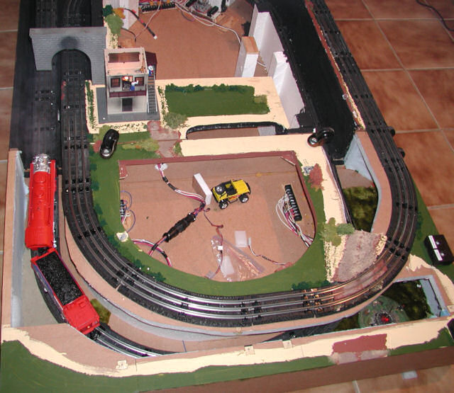
This layout is wired so that when a train enters this tunnel, the hidden track at the bottom of the photo turns on and the train waiting on that track starts ascending to exit the tunnel that would be toward the top of this photo in line with the track going into this tunnel
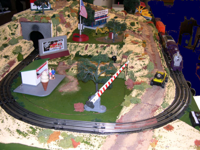
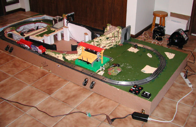
Crossing Gate End of Layout - Above photo shows Uncovered, Below photo shows Hidden
The layout plug strip is powered through a remote controlled 110 V switched socket so all power can be cut. All electrical connections on the display are "quick connect".
Set Up for Test Running
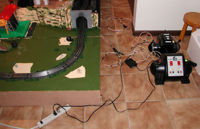
The Postwar ZW Transformer powers the accessories and relay (for
precise voltage control with the 4 variable voltage taps).
The MTH Z-4000 Transformer with #40-4001 Z-4000 Remote Commander
System controls the track power for running engines in conventional
mode. The PS2 engines run at the same speed and start in
forward. While on display the power is stashed under the table
and I can control the trains with the Z-4000 Remote.
Wiring Information
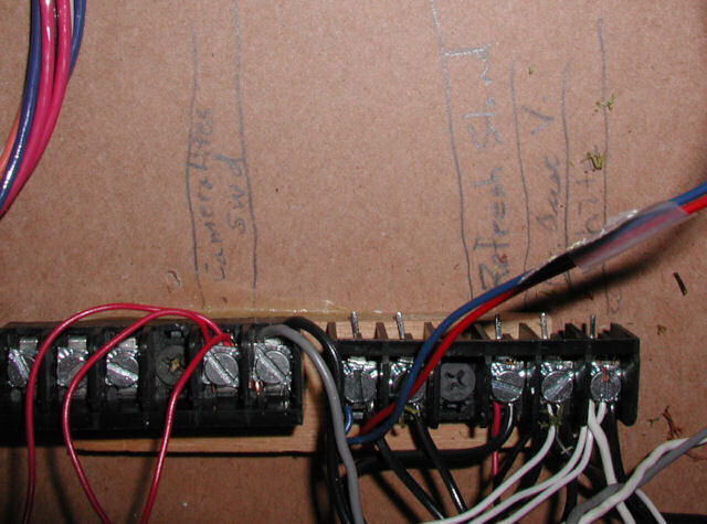
Terminal Block for Crossing Gate End
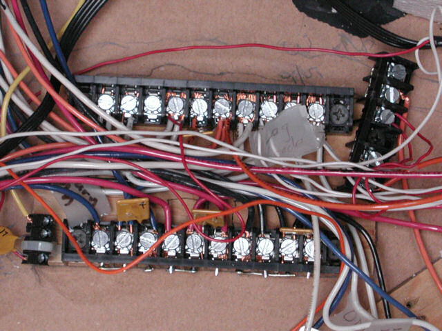
Relay & Terminal Blocks in Center Section
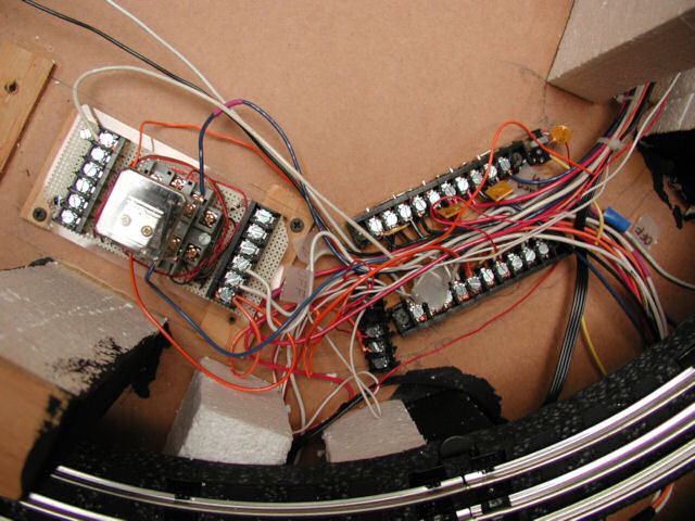
Main Terminals in Center Section
The track and accessory circuits are protected with Polyswitches to prevent disasters. The latching relay controls the hidden track ON and OFF.
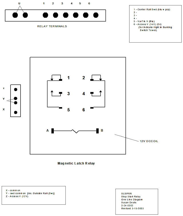
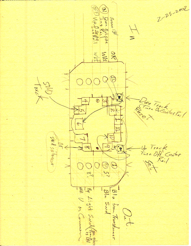
Relay Wiring Diagram
Relay Scratch Paper
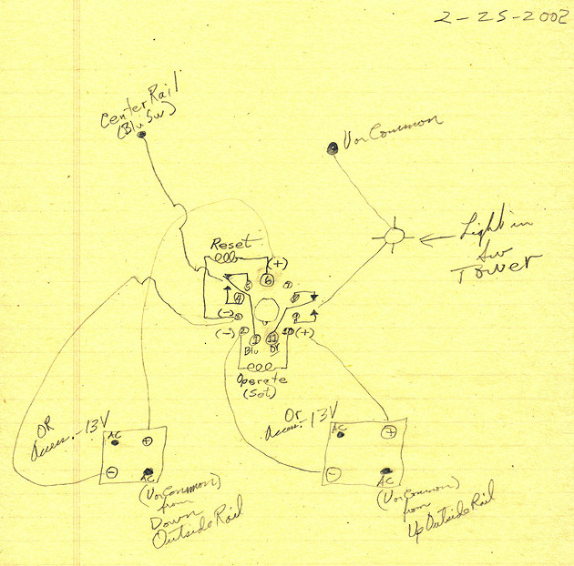
Relay Terminals Scratch Paper
The indicator light in the burning switch tower was replaced with a flood light in the scenery.
Wiring Materials and Color Coding
Materials needed for Relay wiring
1 Magnetic Latch Relay - 2 pole 12 VDC Mouser Part #528-2507-6
Magnacraft # W250ML2CPX-6
1 relay Socket w screw terminals Mouser Part #528-465
2 full wave rectifiers Mouser #583-DB101
Polyswitches (for short circuit protection with auto reset)
1/2" long standoffs w 6-32 machine screw thread Mouser #534-2210
6-32 round head machine screws
Wiring Color Code Conventions
Electrician's color code for ac power is:
white or grey for neutral/common
black, red, blue for power (variable voltage terminals)
purple for switched power wire
brown, orange, and yellow are good for accessory voltage
Low Voltage color code for dc power is:
- black for negative/ground
+ red for positive/variable voltage
Return to Main Disappearing Layout. Click for Construction Details.