Toy Train Layout Wiring - Engine Safety Relays
| Basic | Intermediate | Advanced | Wire Management | Bus Wiring | 120V Train Room |
| Glossary | Wire Sizes | Switches | Load Calculations | Soldering | Troubleshooting |
Bridges Wired to Control Track Power
with Relays for Engine Protection
see Lionel postwar 316 Lift Bridge with 022 Turnout Protection
When an access bridge can't switch the track power, the bridge can switch a relay.
Run Room Wire Color Coding
Black and Red #12 for outside Main Tracks
Variable Voltage, White for all Commons,
Red #16 for Z-Stuff Switch Machines
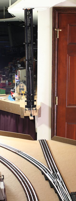
Lift Bridge with Lift Assist Serving the Two Main Lines
(located at South end of
Run Room)
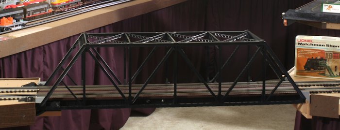
Atlas O 3 Rail Double Track Pratt Truss Bridge Kit
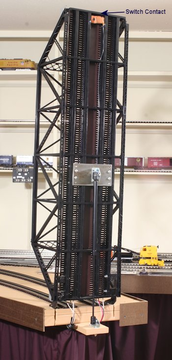 |
 The bridge acts as a switch for the Common that trips the 2 relays for the two isolated area center rails. The protected track is long enough to prevent an engine from running into hole. 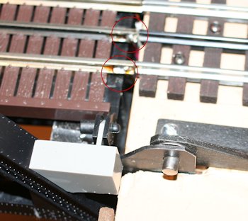 Wires are soldered to bridge track. |
See Access Bridges used as Switches
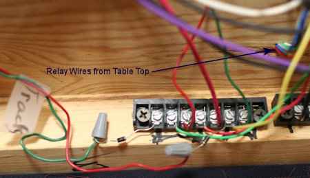
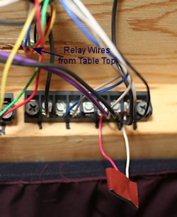
Wiring Bus for Black and Red Mains with
Z-Stuff DZ-1008 Relays
The Black track is the outside Main, the Red track is the inside
Main, and the Purple wires are
for switched track. The white wires are Run Room commons.
The "gizmo" at the
bottom left of the photo is an original
MTH
DCS Filter.
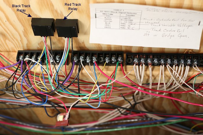
Z-Stuff for Trains DZ-1008 SPDT Relay
Module
(used as a stand alone relay - Requires 10-18 VAC, Relay Contacts
rated 10A 24VAC)
Wiring for Engine Protection with Open Bridge
| Relay Wire Color | Function | Function for Engine Protection with Isolated Center Rail |
| RED BLACK GREEN YELLOW BLUE GRAY WHITE |
12-14 VAC COMMON tie to RED not used Relay - COM Relay-NC (not used) Relay - NO |
Red 13 VAC terminal for Z-Stuff
Switch Machines White (outside rails) Red 13 VAC terminal for Z-Stuff Switch Machines Red or Blue Variable voltage power from Control Center Purple to center rail (off when bridge is open) |
Lift Bridge with Lift Assist Serving the Outside Main Line
(located at North end of
Run Room)
| This
bridge
needs two circuits to prevent an engine running into an open hole. With the bridge closed the straight path and curved path through the turnout are both live. With the bridge open and the turnout lined for the straight path, the protected track is dead. With the bridge open the turnout lined for the curved path, the protected track is live. 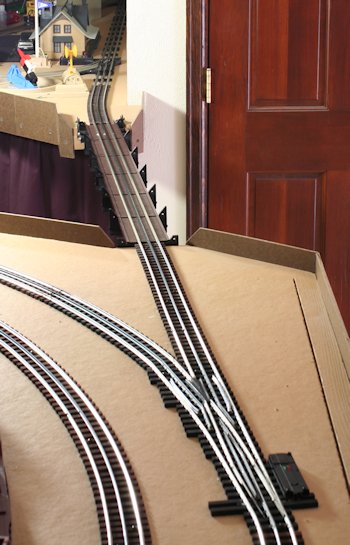 |
 |
Protected Center Rail Through the
Turnout
The rail between the turnout and bridge opening is too short to keep
an engine from
coasting into the hole so the protected track had to extend north of
the turnout.
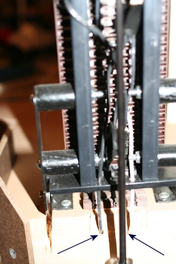 |
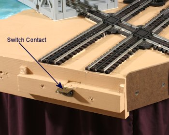
The black and
white wires to the left feed the bridge rails. The black wire is the live feed from the north table. They slide into the table holes when the bridge is lowered. The bridge is fed by the same wires soldered to the track. 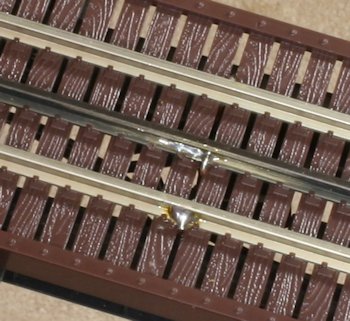 |
| When the bridge
is lowered, the copper strip on the far side connects the Commons/White. The wide copper strip on the near side acts as 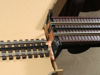 |
a switch by
closing the circuit between the black center rail voltage and the purple switched voltage. 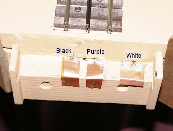 |
 |
 |
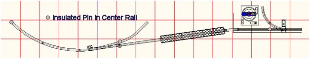
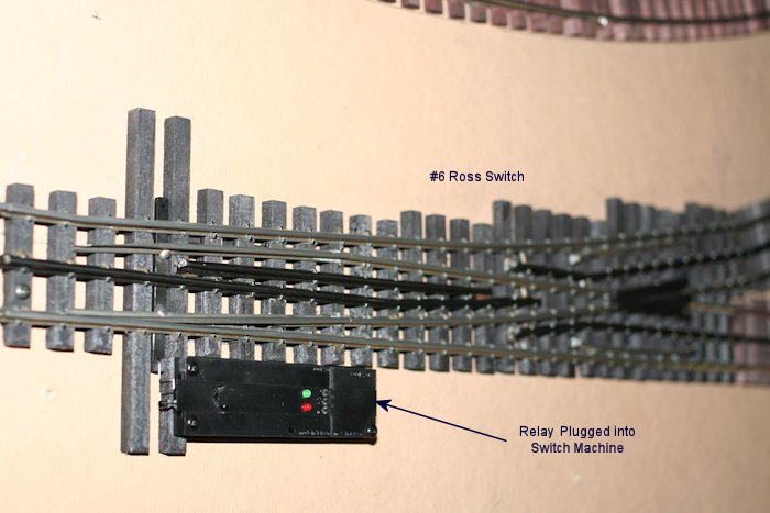
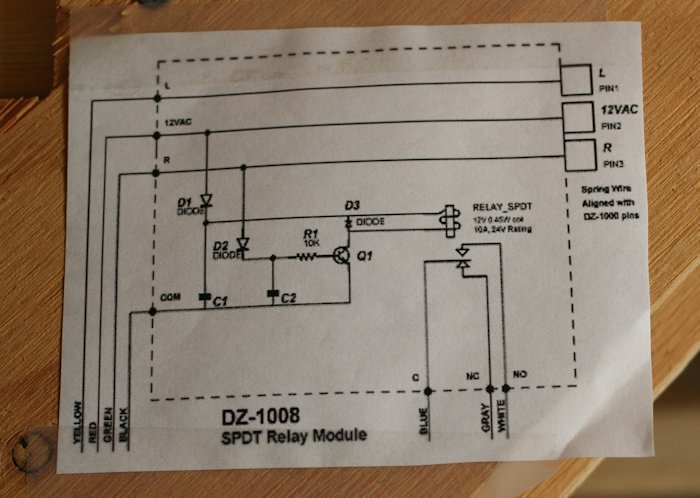
From Z-Stuff for Trains - The diodes must be added to prevent early drop-out when switch motor is wired for non-derailing operation.
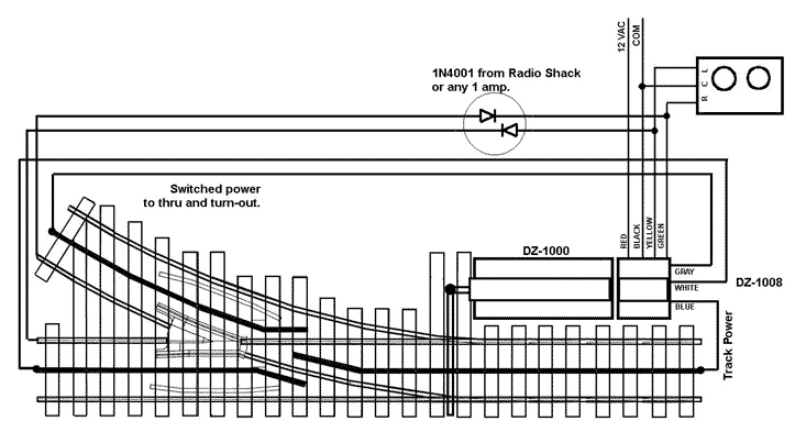
This diagram is posted at z-stuff.net titled "DZ-1000 & 1008 Non-Derailing Operation With DZ-1008 Track Power Control".
This Z-Stuff Relay Diagram is Posted Near Relay for Reference
For Track Protection Zone:
Blue Com wire goes to Black center rail variable voltage source.
Gray NC wire is not used.
White NO wire goes to Purple Switched center rail.
Yellow Relay wire ties to Red Switching Rail for Straight Path.
Green Relay wire ties to Green Switching Rail for Curved Path.
Red Relay wire ties to Red 13 VAC terminal for Z-Stuff
Switch Machines.
Black Relay wire ties to track White Common
| Question? Contact the SSPRR COO (Chief Operating Officer) using the email button to the right. (If email link is absent, please enable JavaScript.) |
|